Seal pots/Condensate chambers are available in carbon steel to ASTM A 106 with Zinga coating equivalent to hot dip galvanized, Epoxy, Silver Coat etc. Stainless Steel to ASTM A 312 Piping code, P22 and other alloy steel fabricated from Seamless pipe with inside cleaned and checked to assure desired volume. Standard pipe sizes are 2" to 6". Connection fittings are NPT or welded socket adaptors, Butt Weld etc. The half coupling connections are jig welded inside and out at 90 degrees to assure safety, provide proper alignment and ease the task of installing.
Note :
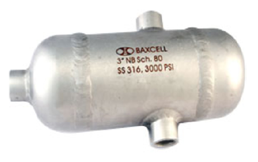
BAXCELL provides Electro Polish finished for stainless steel Pots. All Headers are Laser Marked, wherever possible.
Weld joints are Argon welded as per ASME SEC IX by qualified welding personnel. All headers are 100% hydrostatically / pneumatically tested at applicable pressures and also 2% samples are subjected to Dye Penetrant Testing. The following can be offered upon request.
1) Weld location map / WPS for approval.
2) UT /Radiography test can also be offered upon request.
ISO/ISA standards are typically followed unless otherwise specified.
EN10204/3.1b Test Certificate will be furnished. Typical industry applications include: Refineries, Power plants, Chemical & Petrochemical, Steel plants and other Process industries.
Installation can be either vertical or horizontal lines between the primary (Flow Meter) and the secondary (transmitter/gauge) to act as barrier to the line fluid permitting direct sensation of the flow conditions. Units should be mounted at the same level minimizing possible error that could arise due to unequal head of fluid in the connecting pressure lines.
Initial sizing of the required level in the seal pots is somewhat subjective. The basic rule of thumb is that the level in the chambers should equal the total volume of condensate in the transmitter and the sensing lines. This also complies with ASME requirements. Exact capacity is also contingent on a number of other issues including: Relative humidity, Dew point, Pressure, Flow rate, etc. Standard maintenance includes draining/filling as necessary.
To obtain a quote, following information would be required
Pipe size, Pipe schedule, MOC, Style (location and number of taps) and Quantity. |
|